

Accurate Application and Placement of Chemicals on Lawns
ID
BSE-318NP (BSE-377NP)
Pesticides and fertilizers used in landscape management are normally applied as a liquid through spray equipment, or as a granular formulation through dry application equipment. Each method and type of equipment has advantages and disadvantages. Selection of specific application equipment depends upon economics, availability, and suitability for the intended use.
Liquid Application Equipment
Over 75 percent of all pesticide applications are made as liquid sprays. Spray equipment ranges from simple hand-operated, non-powered applicators to complex multi-nozzle, powered boom sprayers. You must balance the scope of the chemical application needs, efficiency, and economics when selecting equipment. No single machine will provide for every specific need. Several types and sizes of equipment may be necessary for safe, effective, and efficient application.
Hand-Operated, Non-Powered Sprayers
This type of equipment requires no power source to pressurize the unit. Most of the following are inexpensive, require minimal maintenance, and are simple to operate.
Hose-end. A small container with chemical is attached to a garden hose. The chemical is drawninto the water by venturi action as water passes through the hose end. Hose-ends are suitable for application to small turf areas, shrubs, and small trees.
Hose-ends naturally require access to a water source. They are suitable for most sprayable formulations, but are most effective for materials that are soluble in water. Formulations requiring agitation, such as wettable powders, must be frequently shaken. Hose-ends are not effective or suitable for large areas. Hose-ends should not be used on tall trees because the sprayer will not operate at near vertical positions. Changes in water pressure significantly alter output and uniformity. These sprayers are very difficult to calibrate. Hose-ends are probably not the best choice for routine pesticide application.
Compressed Air Sprayer. Compressed air sprayers are available as hand-held or back-pack units. These sprayers consist of a small container (1 to 5 gallons in volume) attached to a short hose and spray wand (Figure 1). The wand normally contains a single nozzle, but multi-nozzle sprayers are available. Nozzles that are adjustable from a fine mist to a solid stream are common for homeowners. The unit is pressurized with a handoperated pump and is capable of developing high pressures.

Compressed air sprayers are suitable for small landscapes, shrubs, small trees. These small units are especially useful for spot spraying and for applications to areas inaccessible to larger application equipment. The sprayers are suitable for applying most formulations, but those requiring agitation (such as wettable powers) will need frequent shaking.
Compressed air sprayers require frequent pumping (Figure 2) to maintain constant pressure. Loss of pressure during spraying significantly alters output. Pressure limiting valves and pressure gauges increase accuracy and reduce pressure fluctuation during operation. Regular maintenance is required during continued operation. If the unit has metal parts, take care to prevention corrosion.

Wick Applicators. These specialized applicators deliver postemergent herbicides. The herbicide is gravity fed from a reservoir to a sponge or rope wick (Figure 3). The wick is wiped on the weed leaving a thin film of herbicide. Wick applicators provide an excellent method for applying non-selective herbicides around or under trees and shrubs, where drift to the nontarget plant may be harmful. Wick applicators must be cleaned frequently and used only with watersoluble herbicides. In most cases, an applicator can do the same job with a small compressed-air sprayer fitted with a shield (commercial or homemade).

Power Sprayers
Power sprayers require an auxiliary gasoline, electric or solar power source to pressurize (a pump) and deliver the liquid. Most power sprayers are equipped with tank agitators (constantly mixes the spray solution) and pressure regulators (eliminates pressure fluctuations). Many contain elaborate nozzle systems. Power sprayers are relatively expensive and complex depending upon size, and accessories. They require frequent maintenance, but are a necessity for applying pesticides to large areas.
Low Pressure Sprayers. Low pressure sprayers (10 to 200 psi) are the most common and versatile power sprayer used in landscape application (Figure 4). Sprayers may be equipped with a single, handheld nozzle or have a multi-nozzle boom for rapid application over a wide area. They are used to apply chemicals to turf or trees, and suitable for all sprayable pesticide formulations. They can also be easily adapted for liquid fertilizer applications.

High Pressure Hydraulic Sprayers. These sprayers generate relatively high pressures (>200 psi), are equipped with a single nozzle (Figure 5), and use all pesticide formulations. High-pressure sprayers are used to apply sprayable-formulation products when a treatment must penetrate dense foliage or reach the tops of tall trees. In addition, they may be adapted for soil injection of both pesticides and fertilizers.

Controlled Droplet Applicators (CDA). Liquid is precisely metered through a nozzle onto a spinning serrated disk. Centrifugal force throws the liquid out in a very uniform droplet size. CDA's (Figure 6) are best suited for herbicide and insecticide applications. The resulting droplets are so small they are difficult to see. These units have a low output making them advantageous for use in areas where water is limited. Their use in landscape maintenance has been limited, due to expense and maintenance and because of the risk of drift posed by small droplets, but improvements in CDA technology has increased interest in their application.

Nozzles for Sprayers
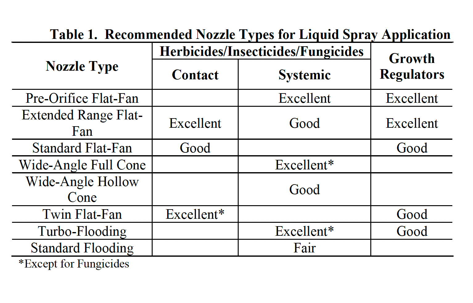
Nozzle selection is one of the most important decisions of chemical application. Nozzle type determines not only the amount of spray applied to a particular area, but also the uniformity of the applied spray, the coverage obtained on the sprayed surfaces, and the amount of drift that may occur. Each nozzle type has specific characteristics and capabilities and is designed for use under certain application conditions.
Remember, that a single nozzle type and size is not ideal for every application situation. The selected nozzle needs to be evaluated for effectiveness, uniformity and potential drift. Tables 1 and 5 (at the end of publication) can be used for selecting the correct nozzle for an application.
Flat-fan nozzles are used for most broadcast sprays of pesticides and fertilizers. These nozzles produce a flat oval spray pattern with tapered edges. They are available in various standard spray fan angles and are usually spaced 20 to 30 inches apart on the boom at a height range of 10 to 30 inches. Recommended boom heights for standard spray angles are shown in Table 2.
Standard flat-fan nozzles have a suggested operating pressure from 30 to 60 psi. Extended range flat-fan nozzles operate over a wider range between 15 to 60 psi. In general, the ideal operating pressure for a nozzle is in the middle of its pressure range. However, the ideal operating pressure for extended range flat-fan nozzle is between 15 to 30 psi. In this range, the nozzle will produce medium to course droplets that are less susceptible to drift than finer droplets produced at pressures of 40 psi or greater. Flat-fan nozzles are also recommended for some foliar applied herbicides and fungicides at pressures of 40 to 60 psi. These high pressures will generate finer droplets for maximum coverage on the plant surface, but will also significantly increase the possibility of drift. Appropriate precautions must be taken to minimize drift effects anytime you apply small spray droplets.
The pre-orifice flat-fan nozzle (Figure 7) reduces the volume of driftable droplets under 200 microns by 40% when compared to other flat-fan nozzles using the volume mean diameter (VMD) at a pressure of 35 psi. The pre-orifice flat-fan nozzles are considered "Medium" sized droplets while the same orifice size in the extended-range flat-fan nozzles are considered "Fine" droplets (Figure 8).


Because the outer edges of the spray patterns of flat-fan nozzles have tapered or reduced volumes, nozzles must be carefully aligned and at the proper height, so adjacent patterns along the boom will overlap to obtain uniform coverage. The most effective pattern is achieved when overlap is 30 to 50 percent of the nozzle spacing. Due to the uniform pattern, when correctly overlapped, the flat-fan nozzle is generally the best choice for the broadcast application of herbicides.
Wide-angle full cone nozzles provide a uniform, circular pattern at pressures from 15 to 40 psi. Droplet sizes are larger than other nozzle types of the same capacity, making it a good choice to reduce drift. Mount the nozzles at a 45 degree angle and 100 percent overlap for an excellent balance of uniform distribution and drift control.
Wide-angle hollow cone nozzles have a large nozzle orifice that reduces clogging and a dual chambered design, which produces large droplets. The nozzles produce a circular pattern at pressure ranges from 20 to 50 psi. Mount the nozzles like the wide-angled full cone. However, the spray pattern from the wide-angle hollow cone will not be as uniform as a full cone.
The twin flat-fan nozzle design incorporates two flat-fan nozzles, one 30 degrees forward and the other 30 degrees backward mounted in one nozzle body. The dual angle improves foliage penetration and improves spray coverage. Recommended to be used from 30 to 60 psi, the twin flat-fan nozzle produces small droplets for more thorough coverage.
Standard flooding nozzles produce a wide-angle flat-fan pattern and are commonly used for applying fertilizers and mixtures of herbicides and liquid fertilizers. The nozzle spacing on the boom for applying herbicides and fertilizers is generally 40 inches. Flooding nozzles should be operated within pressures from 8 to 25 psi for maximum coverage and drift control. Changes in pressure will affect the width of the spray pattern more with this type of nozzle than with flat-fan nozzles. The distribution pattern of standard flooding nozzle is usually not as uniform as a flat-fan nozzle. The most uniform pattern is obtained when flood nozzles are oriented to spray at about 45 degrees above the horizontal and at a height to obtain at least double coverage or 100 percent overlap.
The Turbo-flooding nozzle is constructed with a preorifice and a turbulence chamber that produces a flat-fan spray pattern and larger droplets. At common operating pressures, the Turbo-flooding nozzle produces droplets that are 30 to 50% larger than those of a standard flooding nozzle. A standard flooding nozzle has heavy edges on the spray pattern and makes a uniform spray pattern difficult to achieve. The Turbo-flooding nozzle reduces the heavy edges and maintains an uniform spray pattern more easily, even as the nozzle wears.
Nozzles can be made from several materials. The most common are brass, nylon, thermoplastic, stainless steel, and ceramic. Stainless steel and ceramic orifices will last longer than brass or nylon and will generally produce a more uniform spray pattern over an extended time period. Plastic nozzles with stainless steel or ceramic inserts offer an alternative to solid stainless steel nozzles at a reduced cost. Thermoplastic nozzles have good abrasion resistance but swelling can occur with some chemicals and the nozzles are easily damaged when cleaned.
Since most nozzles are only effective over a limited range of pressures and the orifice dictates output (within limits), selecting both the right type of nozzle and the proper orifice size is critical. Several nozzle manufacturers provide catalogs that show typical sprayer setups and nozzle operating parameters. These catalogs are guidelines but calibrating and fine-tuning the sprayer is required and must be done by the operator.
Nozzle Droplet Sizes
Spray drop size is one of the most important factors affecting drift. Good coverage is essential for insecticides and fungicides because of the small size of the target organism. Fine-to-medium size droplets are desirable when applying insecticides and fungicides because they provide better coverage. Fine droplets, however, are difficult to deposit on the target, so they may remain airborne and drift long distances because of their light weight and small size.
Spray droplet diameters are measured in micrometers. A micrometer is approximately 1/25,000 of an inch and is usually referred to as a micron. For reference, the thickness of a human hair is approximately 100 microns. Droplets smaller than 150 microns in diameter pose the most serious drift hazard. Drift is far less likely to be a problem when droplets are 200 microns and larger in size. The same study indicates that spray particles under 50 microns in diameter remain suspended in the air indefinitely or until they evaporate. They should be avoided because there is no way to control deposition of very fine droplets.
Table 3 provides information on the effect of droplet size on coverage. Table 4 provides information on droplet evaporation and the distance various drop sizes will travel before evaporating.
Table 4 shows some characteristics of various size droplets. Decreasing the droplet size from 200 to 20 microns will increase coverage by a 10-fold factor, but Table 4 shows that a 20-micron water drop will travel less than 1 inch before it completely evaporates in less than 1 second. Droplets less than 100 microns in size obtain a horizontal trajectory in a very short time and evaporate very rapidly. The pesticides in these droplets become very small aerosols, which will move up into the atmosphere and will not fall out until picked up in falling rain. Droplets over 150 microns in size resist evaporation to a much greater degree than smaller droplets due to their larger volume. From these and other research results, we can conclude that there is a rapid decrease in the drift potential of droplets as their diameter increases to about 150 microns.
Several factors determine if a spray particle will deposit on the surface of a plant. Very small droplets (less than 50 microns) are collected efficiently by insects or by needles on coniferous plants but tend to remain in the airstream and are carried around stems and leaves of weeds. Medium size droplets applied when there is some air velocity will deposit more efficiently on stems and narrow vertical leaves such as grasses, while large droplets will deposit most efficiently on large flat surfaces such as broadleaved plants.
Be sure to review the pesticide label regarding droplet size requirements. Labels may specify a droplet size because of coverage requirements and in order to manage drift. When a spraying system is configured to release large droplets, coverage is usually reduced. As a rule, systemic herbicides work very well with large drops. When applying contact type fungicides for disease control, a smaller drop may be needed due to the need for better coverage.
A Range of Sizes
In reality, a range of droplet sizes can effectively deposit pesticides on the variety of plant types, sizes, and shapes encountered. For instance, here is how different size droplets vary in their effectiveness:
- To effectively control pests, the actual range of droplet sizes will depend on the specific pesticide being used, the kind and size of the target plant, and weather conditions. Some new nozzles are specifically designed to reduce drift by reducing the amount of small, driftable fines in the spray pattern.
- Insecticides and fungicides generally require smaller droplets than herbicide applications to obtain adequate coverage of the target. Experimental results with foliar herbicides suggest that droplet sizes in the range of 100 to 400 microns do not significantly differ in weed control, unless application volumes are extremely high or very low. Exceptions to this guideline may exist for specific herbicides.
Droplet size classification
Droplet-size information is useful for determining the correct nozzle for an application and pesticide. A classification system is used to define nozzle output (Table 6). Nozzle manufacturers use this standardized system to indicate the droplet size of their nozzles for different orifice size and pressure combinations. Product labels sometimes use the system to recommend appropriate droplet sizes to be used with their products.
For example, assume that an herbicide label recommends using a nozzle producing “Medium” sized droplets. From the nozzle manufacturer’s chart (Table 7), the applicator can select any nozzle and pressure combination with the “Medium” or yellow classification. This system allows the applicator to use many different combinations of nozzles and pressure settings, achieve the desired droplet size, reduce drift, and provide adequate coverage required for control of the pest.
Spray Volume and Pressure for Foliar Herbicides
Some applicators opt to reduce the spray volume when applying foliar herbicides in an attempt to save time. Reducing the spray volume will increase the herbicide concentration of the finished spray mix so that the same dose of active ingredient is applied per unit area. However, , research has shown that control of some broadleaf weeds with contact herbicides may be reduced if the spray volume is reduced. Conversely, reduced volumes have little effect on weed control with most systemic herbicides, as long as the chemical is applied at the recommended rate.
To compensate for reducing spray volume, some applicators will increase spray pressure from 30 to 40 pounds per square inch (psi) to 50 to 60 psi, believing they can “drive” smaller droplets into the turf canopy to increase coverage. But smaller droplets are more prone to drift. Additionally, many of these smaller droplets will quickly lose their velocity and evaporate before they reach the target. Small droplets have low momentum and insufficient energy to be driven into a plant canopy, such as a stand of turfgrass. Therefore, increasing pressure should not be used as a substitute for reducing spray volume. It is recommended to maintain pressures below 40 psi and, if you need better coverage, increase spray volume.
Technology to Improve Spray Accuracy
The pesticide application and turfgrass industries continue to strive for ways to eliminate turf pests while protecting the operators, those in contact with the turf and the environment. For example, manufacturers continue to use computer technology to calibrate spray equipment, monitor spray coverage rate, and to help make decisions for pesticides, such as when to use or what products and rates would be most effective.
Spray Controllers. Spray controllers compensate for ground speed variations encountered in turf terrain that cause the applicator to speed up or slow down. Most systems monitor travel speed via magnetic sensors or radar devices and measure the flow of spray solutions through an electronic flow sensor. This information is relayed to a microprocessor (Figure 9) which automatically regulates a control valve to achieve the desired application volume.

Most spray controllers have boom sections that are individually monitored, so when a section is shut off, the controller automatically compensates to correct the application volume for the remaining sections.
Spray controllers are excellent add-on equipment, but are limited in the range of travel speed variation they can correct for due to the recommended range of nozzle pressures. This means that controllers have limitations and can at times be pressurizing nozzle output to the point that small driftable spray particles become a problem or pressure is too low to achieve sufficient spray pattern.
Direct Injection Systems. Direct injection systems have the potential to give a sprayer infinite rate control of pesticides. The system uses water or pesticide carrier from the spray tank and the pesticide is metered into the boom at the desired rate depending on speed and other inputs (level of infestations, etc.).
Direct injection systems have several advantages that controllers and manual power sprayers do not. First, the pesticides are not mixed in the spray tank. This eliminates potential exposure of pesticide concentrates at mixing time. However, the greater benefit is that rinsates and leftover tank solution can be practically eliminated.
Several other advantages such as the carrier can be independently set, a single desired pressure can be selected that matches the desired droplet size for your spraying needs. Nozzle pressures can be maintained to reduce drift potential and a uniform spray pattern can be maintained.
Since the pesticide formulations are kept in separate containers, the use of closed mixing systems will become standard. The pesticide material not used during a season may have the option to be returned, further reducing pesticide storage and inventory.
Direct injection systems have been under continual investigation. The greatest concern is the accuracy of the metering device. Since pesticide formulations vary greatly with specific density and viscosity, an accuracy metering device is essential. Manufacturers have several methods to assure correct metering is accomplished. Some calibrate the metering device for each chemical used. Some have identification cards that change the metering device based on pesticide characteristics. Some use a small flow meter that monitors the metering device as a secondary check.
Probably the greatest benefit of these systems lies in the future. As the industry develops sensors that can identify pests and their concentration, a direct injection system can use this information to apply pesticide rates that will effectively control these pests without having to use a uniform broadcast rate over an entire area for maximum control. Thus, areas with little infestation will receive little or no pesticides, therefore reducing the amount of pesticide used. This concept is considered prescription application.
Closed Mixing Systems. Closed mixing systems minimize the amount of exposure people receive while mixing and transferring pesticides. Most systems are portable units that fit on top of the tank opening or are used with an inductor (Figure 10). Some systems allow operators to mix bagged pesticides into a sprayer without opening the bag. When properly used, the system eliminates the possibility of inhaling pesticide dust.

Others transfer liquid products from the original container into a sprayer tank. These systems clean 1, 2.5, and 5 gallon containers to triple rinse standards. The empty pesticide container is inserted upside down and the unit spout washes fresh water into the container and residue is deposited in the spray tank. Sprayer Shields. In searching to find a method to control drift while still providing flexibility when you can spray, shielded booms have become increasingly popular. The shields fit over the boom (Figure 11) in either mounted or walking booms. When properly adjusted, the shields don't contact the spray, but minimize the effect of wind on the spray pattern and thereby reducing drift potential.

Boom Height Control. Since boom height is critical for spray pattern uniformity, several manufacturers have included manual or automatic adjustable booms. The automatic boom control uses a sonar sensor mounted close to the end of the boom. As the sprayer transverses the surface, a sound wave is emitted and reflected from the turf, telling the sensor how far the boom is from the ground. If adjustments are needed, an electronic screw actuator automatically corrects the boom height.
Granular Application Equipment
The types of equipment available to apply granular pesticides or fertilizers is less extensive and the machinery is less flexible than what is available to apply liquid materials. Machines constructed of stainless steel, heavy plastic, or other noncorrosive material will provide longer service. Granular spreaders can be used to broadcast seed and overseed grass.
Granular applicators have several advantages. They are simple in design, have few moving parts, and are easy to clean, maintain, and repair. Since the pesticides used are ready-to-use, no mixing is necessary. In addition, granules are less likely to drift and settle quickly after application. Applicator exposure hazard is reduced because there is no spray, little or no dust, and the active ingredient percent is low.
However, spreaders also have some drawbacks. You must recalibrate your equipment for each granular formulation used and, compared to calibrating spray equipment, spreader calibration is relatively difficult. In addition, rotary spreaders sometimes give poor lateral distribution.
Granular formulation pesticide products are relatively safer to use than their liquid counterparts. Granular formulations usually have a low percent of active ingredients, which reduces the possibility of serious damage resulting from overapplication or accidental exposure. Exposure risk is also reduced due to the fact that these materials are dry and particle size is relatively large, so the risk of skin absorption is very low.
However, granular products also present several limitations. The volume of the carrier cannot be adjusted as with liquid materials, so the application device must be calibrated for each product used. In addition, the actual product must be used during calibration. As a result, operators must take steps to avoid exposure and environmental pollution. Fewer products are available in granular form than in liquid formulations. Granules will not adhere to foliage. Spreaders may not apply granules uniformly to uneven surfaces.
Despite the disadvantages, many homeowners and lawncare services use only granular formulations as a marketing advantage to counter some neighbor's or client's environmental concern about spray drift.
Hand-Operated Granular Applicators. Hand-operated granular applicators can be carried or strapped to the operator's chest. These are not recommended for pesticides due to the exposure risks but may be applicable for fertilizers. An adjustable opening at the bottom of the hopper meters the pesticide onto a spinning disk turned by a hand crank. The speed at which the operator turns the crank determines the width of application. These spreaders are relatively inexpensive and easy to use. Calibration is complicated because of operator variation in walking and cranking speeds.
Centrifugal Spreaders. The pesticide is metered onto a spinning disk. When the pesticide strikes the disk, it is thrown by centrifugal force, in a relatively uniform pattern around the spreader. The speed of the disk determines the effective spreader width. The disk speed is controlled by ground speed with ground driven applicators. Some spreaders use an external power source, such as a small electric motor or power take-off (PTO), which drives the disk. These "powered" spreaders (Figure 12) are mounted on utility vehicles or tractors and disk speed is independent of ground speed.

Drop Spreaders. Drop spreaders contain a box or hopper mounted between two wheels. As the spreader is pushed, the wheels turn a baffled cylinder within the hopper which meters the granules through adjustable openings at the base of the hopper, allowing the granules to fall on the ground.
The swath width of drop spreaders equals the width of the hopper and is usually between three to five feet. Output is controlled by adjusting the size of the opening on the bottom of the hopper and, to a lesser extent, ground speed. Some drop spreaders can be pulled behind a utility vehicle, but the majority of spreaders are pushed by the operator. Drop spreaders are useful for applying granular materials in areas where the swath of a centrifugal spreader is too wide.
Drop spreaders have a low coverage per unit time (low capacity) because of the narrow swath. They are also prone to skips and overlaps of applied materials. The problem of skips and overlaps is reduced by applying half rates of the material in two, perpendicular applications (Figure 13). This, however, takes twice as long to cover an area.

Air Spreaders. Air spreaders meter granules through an orifice, or with a fluted roller, into a venturi where they are suspended in an airstream and carried through hoses to deflectors mounted on a boom (Figure 14). At the deflectors, the granules are distributed in a pattern similar to that of a flat-fan nozzle. When properly calibrated, air spreaders can uniformly distribute materials over a wide range of application rates.

Calibration
Accurate calibration of application equipment is critical for every successful pesticide application. Inaccurate or sloppy calibration has economic, legal, and environmental ramifications. Under application results in potential poor pesticide efficacy, repeated applications, and reduced profit margin. Over-application increases the possibility of damage to the site, replacement of sensitive landscapes, lawsuits, and is a violation of FIFRA (Federal Insecticide, Fungicide & Rodenticide Act). Over-application of pesticides could result in civil and criminal penalties. It is also costly.
Calibration of Liquid Application Equipment
A preseason visual check of a sprayer is not adequate for accurate application, nor is the fact that the equipment and nozzles are new. A Nebraska survey found that only one of six turfgrass sprayers were applying pesticides within +/- 5% of their intended application rate. This shows that sprayers must be calibrated frequently to ensure all nozzles have the correct flow rate, are applying pesticides uniformly, and are applying the correct pesticide rate.
Before calibrating a sprayer, service the entire unit, checks for uniform nozzle output (Figure 15) and spray pattern (Figure 16), and determine exactly how much liquid your sprayer tank holds.


Servicing. Clean all lines and strainers, making sure the strainers are in good condition and are the correct size for the type of chemical formulation being applied. Inspect all hoses for signs of aging, damage or leaks and hose clamps for corrosion.
Check the pressure gauge to determine if it is working properly (Figure 17). Does the pressure remain constant and does it read zero when the pump is shut off? The actual accuracy of the gauge is not as important as its ability to give the same pressure reading each time. At least once a year, preferably at the beginning of the spraying season, check the gauge against another gauge which is known to be accurate.

Boom pressure may be lower than the pressure at the pump or sprayer manifold. To determine pressure loss, operate the sprayer at a known pressure, then install a gauge on one of the nozzle outlets on the boom and record the lower pressure (Figure 18). Check nozzle pressure at several operating pressures to develop a nozzle pressure table. If variation exists, examine the plumbing system.

Nozzle Output and Spray Pattern. Check for uniformity of nozzle output and for consistency of spray angles, spacing and height. To check for uniform nozzle output, install the selected nozzles, partially fill the spray tank with clean water, and operate the sprayer at a pressure within the recommended range. Place a container (for example, a quart jar) under each nozzle and check to see whether all the jars fill in about the same time.
Inexpensive calibration flow meters (Figure 15) are available for direct readings of individual nozzle flow rates as a method to quickly check nozzle output. Replace any nozzles that have an output that varies more than 10 percent from the average of all nozzles, have an obviously different fan angle or distorted spray pattern, or the output is 10 percent greater than the original nozzle discharge rates.
To determine whether an uniform pattern is being produced and whether the boom is at the proper height, use a pattern check tray (Figure 16) or spray water on a warm dry surface, like a paved or concrete surface, and watch the drying pattern (Figure 19). If the pattern is not uniform, some strips or areas will dry slower than others. Effective application requires avoiding skips and major overlaps in the spray pattern. Regardless of how much time and effort has gone into calibration and preparation, a non uniform spray pattern could cause more harm than good.

One method to assure uniform application is to use a spray dye indicator with the tank mixture. This indicator helps the spray operator maintain the proper amount of overlap and detect defective or clogged nozzles. Dye indicators can be an effective additive for hand-held sprayers to aid in obtaining uniform and complete coverage.
Proper swath overlap is easily obtained when the sprayer is equipped with a foam-marking system (Figure 20). They drop foam from the end of the boom, providing a visible cue to the applicator swath. Keep in mind that the distance between the over-lapping swaths should equal the distance between nozzles on the boom. For example, if the nozzle spacing is 20 inches, maintain a 20 inches spacing between the end nozzles on successive passes of the sprayer.

Tank Capacity. Knowing the exact capacity of the spray tank is necessary for accurate mixing of chemicals. The use of an inaccurate tank capacity when determining application rates is a common cause of under and over-application. A tank thought to hold 200 gallons, but which actually holds 250 gallons, results in a calibration error of 25 percent.
The best and easiest way to accurately determine tank capacity is to fill the tank using any convenient container for which an exact capacity is known. If the container capacity is unknown, it can be determined by filling the container with water and weigh it (water weighs 8.33 pounds per gallon). Another effective way of measuring tank capacity is with an accurate flow meter. Flow meters should be checked for accuracy by weighing sample volumes taken over a given amount of time. Regardless of the type of equipment used, two pieces of information are necessary to calibrate liquid application equipment; sprayer output and coverage rate. Sprayer Output per unit time. The output of a sprayer must be determined. The factors involved are sprayer configuration (nozzle placement, number, type, and orifice size) and pressure. This is usually measured in fluid ounces per minute (OPM). Materials needed to measure output are a stopwatch, a container to catch the liquid, and an accurate liquid measuring device calibrated in fluid ounces.
Equip the sprayer with the nozzle or nozzles that will be used in the actual spraying operation. Calibrate the sprayer at the same operating parameters (such as pressure) that will be used on-site. For multinozzle boom sprayers, the output should be measured for each nozzle and then added together to determine the sprayer output.
With the sprayer in a stationary position operate the sprayer for a predetermined amount of time (usually less than a minute) and collect the output in the collection containers (Figure 21). Measure the amount collected and record the value. Repeat this output measurement a minimum of two more times to ensure an accurate determination of output. Use the average of the three recorded values to determine output in ounces per minute (OPM).
If it is more convenient, work with sprayer output in gallons per minute (GPM). Divide the output in OPM by 128 to determine the output in GPM.

This method for determining output can be used for most sprayers. One exception is high pressure sprayers commonly used for application of pesticides to tall trees. These sprayers deliver a relatively large volume of material under very high pressures. Collecting the output in a container is practically impossible. To determine the output of high-pressure sprayers, fill the spray tank with water to a predetermined level and operate the sprayer under actual spray conditions (without fertilizers or pesticides) for a measured time. Record the amount of water needed to refill the tank back to the original level. Repeat this procedure at least two more times to determine the average output.
Coverage Rate. The second piece of information required for accurate calibration is coverage rate or the amount of time it takes to spray a given area with the sprayer as configured. The determining factor is speed. For most large scale spraying operations this is expressed in minutes per acre (min/ac). For smaller applications, it is usually more convenient to express coverage rate in minutes per 1,000 square feet (min/1,000 ft2) (See Coverage Rate example).
Some pesticide labels have specific oz/ac, oz/1,000 ft2, or GPA requirements. For example, a label may specify, "apply this product with a minimum of 60 gallons of water per acre." If the sprayer, as equipped and calibrated, results in an output that is higher or lower than required for a particular pesticide, adjustment will be needed.
Application rate may be reduced by: 1) decreasing the nozzle orifice size; 2) decreasing the spray pressure; and/or 3) increasing the sprayer speed. Conversely, application rate may be increased by: 1) increasing nozzle orifice size, 2) increasing spray pressure, or 3) decreasing the sprayer speed.
To make minor adjustments, change pressure (within limits, based on nozzle/system specifications). To make modest adjustments, change speed—within safe operation limits. To make major changes, change nozzles or reconfigure your apparatus (ex. boom width, release height).
Tank Mixing Pesticides
Once a sprayer has been accurately calibrated, pesticides can be added to the tank (Figure 22). This is often the point at which many errors occur. Mismeasured pesticides or miscalculation of the amount of product to be added can result in gross over or under-application of pesticides.
Errors are often made when dry ounces are not distinguished from fluid ounces. Remember to avoid confusion; Figure 22. Correct tank mixing is essential there are 16 for proper application dry ounces per pound and 128 fluid ounces per gallon. Further, dry ounces are a weight or mass measurement, whereas fluid ounces are a volumetric measurement. Containers used to measure fluid ounces are never appropriate for dry weight measurements. Note that dry flowable (DF) and water-dispersible granule (WDG) formulations are sold with product specific measuring devices. These measuring containers look like those used for volumetric measure; however, the marks indicate weight. Keeping these simple, but often over-looked, points clear is paramount to accurate addition of pesticides to a spray tank.

Product labels normally list rates in the amount of product required for a given area or application. Universities, Federal and State agencies, however, often express recommendations on an active ingredient (AI) basis. Because pesticides are very rarely formulated as 100 percent active ingredient, the amount of product and amount of AI are not synonymous. For example, to apply a 50W product at a rate of 1-pound AI per acre, it is necessary to apply 2 pounds of product per acre since 1 pound of 50W product contains 0.5 pounds of AI. If the operator has applied only 1 pound of the product per acre, the pesticide would have been inadvertently under-applied. Make sure, when adding a pesticide to a spray tank, that the amount needed from the desired rate and what is added to the tank are equivalent.
Decontaminating Turfgrass Sprayers
Sprayers must be thoroughly cleaned inside and out after use. Ideally, a sprayer should be cleaned before switching to a different pesticide or tank mix. Sprayers retain tremendous amounts of pesticide solution. Depending on the size and design of the sprayer, there can be nearly 6 gallons of solution left in a sprayer's plumbing. The parts that retained the most chemical solution are the chemical induction bowl, the booms, the tank and the pump and its related piping.
Tests have shown that triple rinsing the spray tank is better than using just one single rinse. For example, using 100 gallons of clean water in one single rinse to clean a 100-gallon sprayer tank reduced the concentration of the original spray solution from 100% to 5% both in the tank and at the nozzle. If triple rinsing was performed using 33 gallons of clean water per rinse, a concentration of 0.2% to 0.5% was gained. The aim is for maximum dilution with minimal use of water.
Before rinsing a sprayer, read the sprayer manufacturer’s instructions for specific guidance on the best methods for cleaning your equipment. Consult the pesticide label for any special cleaning instructions. Use the protective clothing listed on the pesticide label. Do not allow sprayer rinse water to enter any waterway, field drainage system, or well. If rinsing needs to be done at the mixing/loading site, it must be done on an impervious surface. All contaminated rinse water must be trapped and either used to mix another load of the same pesticide at the label recommended rates, applied to a labeled site, or disposed of at an approved pesticide waste handling facility.
Reducing Cleaning Problems. Rinse water can be minimized by good planning and equipment maintenance. The following are suggestions to help reduce cleaning needs:
- Minimize carryover/cross-contamination problems by having at least two sprayers: one used only for herbicides, and another used only for insecticides and fungicides.
- Carefully plan how much pesticide to mix so that all mixed pesticides are used up when finished.
- Be sure that the sprayer is clean before use.
- Make sure all parts of the sprayer are in good condition. Corroded, cavitated or pitted surfaces are prime areas for pesticide residue to hide. Replace any worn parts.
- Mix the chemicals in the correct order. Some chemicals, when mixed in the wrong order, can actually become more difficult to remove from the equipment. Consult the pesticide label for the proper mixing order.
- Follow any label instructions for cleaning spray equipment.
- Be sure that cleaning solutions contact ALL equipment surfaces.
- Remove and clean filters, strainers and nozzle screens separately from the rest of the sprayer.
Tank Rinse Systems (Low-Volume Tank Rinsing). Tank rinse systems consist of a clean water supply tank mounted to the sprayer and one or more rotating discs or nozzles mounted inside the main sprayer tank. Water is pumped from the clean water tank to the rinse nozzles where the water is sprayed around the inside of the spray tank. These systems are designed for infield rinsing of the sprayer so that the tank washings can be applied to the treatment area.
A tank rinse system can be purchased as an option on some sprayers or as an add-on kit. A sample rinse system layout is shown in Figure 23. A typical rinse system uses 360-degree tank wash nozzles mounted in the top of the tank. These nozzles are available in flow rates of 10 GPM at 20 psi up to 20 GPM at 50 psi. If a spray tank has baffles, at least one rinse nozzle per compartment is needed. In any case, a sufficient number of rinse nozzles should be installed to provide enough rinse water to contact the entire tank interior.
A clean water tank can be plumbed into the sprayer plumbing system to provide the Figure 23. Correct tank mixing is essential clean rinse for proper application. water. This tank should be permanently marked "Clean Water Only" so that only clean water is placed in the tank, reducing the chance for contamination of the rinse system. The tank should be mounted above the pump in order to aid in priming the pump. Ideally, the tank should be mounted on the sprayer.

When using tank rinse systems, check the pesticide label or with the chemical manufacturer to be sure that low-volume rinsing is suitable for the products being used. During the rinse process, open and close the pressure valve and other control valves on the sprayer to ensure that any chemical that may be trapped in the valve is rinsed out. Using the rinse system, run three rinse cycles, making sure the water discharged from the nozzles is completely clear by the end of the third rinse.
Spray Techniques
Be aware of the proper application procedures and consistently follow them. There are also differences in procedures among the various type of equipment.
Power Sprayers. Boom sprayers have good control to a provide uniform and accuracy spray application. Follow the proper procedures to minimize overapplication while improving efficacy.
The first step is to survey the area that will be sprayed. Look for obstacles and sloping or rough terrain. If moveable objects are in the way, remove them. It is best to spray parallel to the length of the field, starting against a square end if possible. Doing so will minimize turning and on/off time. This also allows for more uniform application. Do not spray while turning. Instead, spray the ends (headers) of the turf area after completing the area. Spraying the headers first is a common mistake that results in driving through wet foliage. In some case, traffic can cause turfgrass phytotoxicity from an accumulation of herbicides on the sprayer's tires.
Sprayer speed directly influences application rate. Doubling the travel speed cuts the application rate in half and traveling at half the desired speed doubles the application rate. An accurate speedometer or monitor can help maintain a constant speed.
Monitor the spray pressure to ensure that the sprayer is operating at the same pressure used during calibration, and that it remains constant. Periodically inspect the spray pattern, look for leaks, plugged nozzles and proper tank agitation. Hand-Held Applicators. Hand-held applicators are available in a wide range of lances and nozzles to accommodate different applications. Most single nozzle units are equipped with a multi-purpose nozzle that can be adjusted to produce a cone pattern with a fine spray to a coarse stream. This nozzle is useful for spot treatment of individual weeds or trees, but is not effective for large areas.
Most prefer an even flat-fan nozzle for spraying large areas. The application volume can be varied by selecting a different size of orifice with a known output. When spraying, maintain a constant pressure in the tank and hold the nozzle stationary at the proper height the fan pattern perpendicular to the direction of travel. When using a flat-fan nozzle, waving the spray wand back and forth will result in non-uniform coverage.
Hand-guns require considerable operator skill to evenly spray large areas. Proper delivery and uniform coverage are dependent on walking speed and gun motion. Gun motion consists of waving the gun in a back-and-forth, side-to-side motion. Hold the gun at any angle from 45 degrees to nearly parallel to the ground. The speed at which one walks will influence the gun motion.
Use a gun motion that will hit a target 2 or 3 times with the spray pattern while moving forward. Establish a consistent walking speed that allows for gun motion and reduces fatigue. A good training method to attain a proper gun motion is to practice on a paved area using water in the sprayer and then watch the drying patterns.
Each person who uses a hand-held or backpack sprayer should calibrate it. This is because each user’s walking speed and release height (and therefore swath width) will vary.
Calibration of Granular Application Equipment
Manufacturers of chemicals may provide information for settings on granular applicators, but these should be used only as starting set points. Manufacturers are as precise as possible with calibration guidelines, but there are several variables that must be measured for accurate calibration.
Variables affecting granular application rates are ground speed, swath width, and meter opening. Ground speed will vary on hand-pushed spreaders based on operator walking differences, so each operator should calibrate spreaders individually.
Swath width depends on the type of spreader, and uniform application of the pesticide is dependent on the operator's ability to maintain proper overlap between swaths. The meter opening is adjusted to distribute a certain amount of pesticide for a given speed and swath width. It cannot be accurately set if the operator does not maintain a nearly constant ground speed and swath width. Since different granules have different flow characteristics, granular applicators must be calibrated for each particular material. Because you must use the formulated product when calibrating spreaders, take precautions. If possible, use a collection device or system (ex. work over a tarp). If not, calibrate in a legal/labeled site.
Calibrating granular application equipment is similar to the process described for liquid applicators with several subtle differences. The carrier (water) volume for liquid applicators can be increased or reduced depending upon the particular operation. A granular pesticides concentration is fixed and cannot be adjusted because it is typically formulated with an inert carrier. This requires that calibration be performed for each and every granular product used. Also, the actual pesticide (or fertilizer) must be used during calibration since the size and density of granular products vary. Relative humidity can also affect flow of granules so spreaders should be recalibrated when the relative humidity changes drastically.
The first step in calibration of a granular applicator is to calculate the area to be covered (coverage rate). For drop spreaders, coverage is simply the width of the hopper multiplied by a distance. For example, coverage area of a drop spreader with a 4-foot wide hopper traveling 25 feet is 100 ft2 (4 feet times 25 feet = 100 ft2).
The swath width of a centrifugal spreader is con-trolled by the speed of the centrifugal disk and can be altered by cranking speed of hand-cranked spreaders, ground speed of ground-driven spread-ers, or rotational speed for powered spreaders. Swath width and thus coverage rate by these spreaders is variable and must be determined for the speed used in actual pesticide applications.
To determine the swath of centrifugal spreaders, lay a row of collection vessels on a one-foot spacing perpendicular to the spreader's line of travel (Figure 24).

The containers can be cigar boxes, pie tins, or any similar receptacle. Each container used should have the same dimensions. Load the spreader with the pesticide to be applied and set the opening on a medium setting. Run the spreader, at the speed to be used in actual operation, over the collection containers. This operation should be done at the shop or in an open or paved area, not on the lawn or driveway. Check the collection containers for granules. By observing the amount and distribution of the material in the collection containers, spreader swath can be reasonably estimated. If the material in each container is weighed, distribution and application rate can be checked and adjusted.
The final step in calibrating a granular applicator is to determine the spreader setting required to apply the amount of material, based on the rate coverage determination, to equal the desired rate. To determine the correct setting at which the spreader is to be operated, the machine should be calibrated at the recommended setting, the output collected as outlined in the discussion of determining spreader width and weighed, and the setting adjusted as necessary.
Drop Spreader. Collection of the output from drop spreaders can be accomplished one of two ways. Most commercial drop spreaders come with a calibration pan (Figure 25).

This is attached beneath the spreader so that when the spreader is pushed over the calibration course, the output is collected in the pan. If a calibration pan was not included with the spreader, a catch pan can be fabricated.
Other calibration methods include pushing the spreader over a concrete surface or tarp, collecting the particles applied, and measuring the discharge. However, when a spreader is pushed along a surface dissimilar to landscape, large differences in wheel speed could result in inaccurate application. Using a calibration pan is more efficient and the spreader can be calibrated on the actual surface to be treated.
If the initial setting does not deliver the desired amount, make the appropriate adjustments. If the collected amount is less than the calculated requirement, the setting can be increased or the travel speed of the applicator reduced somewhat. Conversely, a decrease in the output setting, or an increase in speed results in a lower output. Once a setting is found which delivers the desired amount, the output should be collected a minimum of two more times and the average calculated to ensure accuracy.
Centrifugal Spreaders. Use of a calibration pan for centrifugal spreaders is impractical. The normal procedure for collecting output from a centrifugal application is to operate the spreader over a tarp or plastic sheet of known dimensions. Weigh the output. The expected volume for the size of the catch tarp must be calculated. If the tarp is wider than the spreader swath, then coverage is simply calculated as swath width multiplied by tarp length (Figure 26). If the tarp is narrower than the spreader swath, then coverage rate is equal to the catch tarp area. If the initial setting does not deliver the desired amount, then appropriate adjustments will be needed.

Because the speed of travel of ground-driven centrifugal spreaders affects spreader swath, increasing or decreasing speed will affect coverage rate. Adjusting the speed of the applicator cannot, therefore, be used to alter output for a ground-driven spreader. Adjusting travel speed can alter output for mounted, powered centrifugal spreaders or any centrifugal spreader whose disk speed is independent of ground speed.
Operators should remember that it is extremely difficult, if not impossible, to calibrate a granular spreader to deliver exactly the desired amount. Granular pesticides contain low concentrations of the active ingredient to help compensate the inherent calibration inaccuracy. The operator should adjust the settings so that delivery is as close as reasonably possible to the recommended amount. The operator, however, should and must be willing to settle for close. If the desired amount is within 10 percent of the calculated amount, the applicator should proceed with the application confident that they are applying the granular material within a safe and effective manner. To help ensure uniform distribution of granular applicators, some operators divide the rate by two, then, use double coverage. This means apply one-half of the material in one direction and the other half in a direction perpendicular to the first (Figure 13). When this method is used, the granular spreader must be calibrated to apply one-half the desired rate.
Field Operation Guidelines
- Do not drive faster than the equipment is designed for or the terrain will safely allow.
- Check to be sure the pesticide is reaching the target.
- Calibrate your equipment if the label instructs you to apply a specified amount per unit area or volume.
- Check hoses, valves, nozzles, hoppers, and other equipment parts for clogs, leaks, and signs of wear.
- Be sure your equipment is dispensing liquid or granules evenly and uniformly.
- Shut off your equipment before turning and whenever you stop. Many types of application equipment will continue to release pesticide even when not in motion. Also, it is difficult to apply the product evenly as you turn.
- Check the pump and plumbing systems for leaks or loss of pesticide.
- Make sure no obstacle or machine part interferes with pesticide distribution.
- Keep your equipment clean and free of debris.
- To clean or unplug a nozzle or spreader orifice, use compressed air or a soft-bristle brush.
- Never operate a sprayer with the screens or filters removed.
- Do not run a sprayer pump without water.
- Dedicate one sprayer to herbicide use and another to insecticide and fungicide applications.
Looking Ahead
Application equipment for the future will feature increased operator safety, precise application, and protection of the environment. Invest in the future by updating your application equipment and conducting regular maintenance and calibration checks.
By keeping your equipment in good working condition and practicing appropriate pesticide safety and management strategies, you demonstrate your sensitivity to individual workers and the environment. Be a beacon of responsibility.


Determining Coverage Rate
Materials needed to determine coverage rate are area markers, a stopwatch, and a tape measure. 1) Determine the effective spray width of the sprayer. The effective width of a boom sprayer is the product of nozzle spacing and the number of nozzles on the boom. 2) Measure and mark a known distance between 25 and 100 feet. Based on your effective swath width, choose a course distance that will treat a representative area. The calibration distance for self-propelled spreaders should be greater than that used for manual sprayers. Use an area that keeps the “math easy” ex. 200, 500, or 1,000 ft2 for a small device (ex. backpack, drop spreader) and a bigger area (5,000 ft2) for a boom sprayer. 3) Run the sprayer at exactly the same speed to be used on site and record the time it takes to go the measured distance. 4) Repeat this procedure a minimum of two more times to ensure accuracy. 5) Use the average of these three measurements to determine the speed of the sprayer.
From the time needed to travel the prescribed distance and the effective spray width, the coverage rate is:
- Coverage Rate = Time (min) / { Effective Swath Width (ft) x Travel Distance (ft) }
To determine the coverage rate for hand-held or hose-end sprayers, measure and mark a known area (i.e. 4 feet by 25 feet) that is typical of the surface to be applied (Figure 27). Then measure the time required to cover this area. The coverage rate will depend on the walking speed, thus be as consistent as possible. The coverage rate is determined by dividing the time (minutes) by the known area (ft2).
After measuring the total output from the sprayer in OPM or GPM and the coverage rate in min/ac or min/1,000 ft2, then the spray volume can be determined by one of the following:
- oz/ac = OPM x min/ac
- oz/1,000 ft2 = OPM x min/1,000 ft2
- GPA = GPM x min/ac
- gal/1,000 ft2 = GPM x min/1,000 ft2
Example 1. Suppose a groundskeeper has a power sprayer with 12 nozzles (XR8005) spaced at 20 inches apart. Output from each nozzle was collected over 30 seconds. The average of this discharge was 28 ounces (over 30 seconds), 56 OPM, or an equivalent of 0.44 GPM. The individual nozzle discharge was within +/- 10% of the boom average (50-62 OPM).
The spray rig was driven over 200 feet at its desired speed setting of 3 mph. It took 45 seconds to cover 200 feet. The coverage rate was calculated as:
- Coverage rate = (45 seconds x (min/60 sec)) / (20 ft x 200 ft)
= 0.000188 min/ft2
or = 0.188 min/1,000 ft2
The spray volume can be calculated as:
- gal/1,000 ft2 = 0.44 GPM x 12 nozzles x 0.188 min/1,000 ft2
= 0.99 gal/1,000 ft2
or oz/1,000 ft2 = 56 OPM x 12 nozzles x 0.188 min/1,000 ft2 = 126 oz//1,000 ft2
The desired application volume was 1 gal/1,000 ft2 so this spray unit is ready to go.
Example 2. Suppose an applicator is using a lawn spray gun and has collected 1.3 gallons from the gun in 30 seconds. The gun output would be 2.6 GPM.
An area is flagged that is 30 feet by 40 feet and it takes about 30 seconds to make an application to this 1,200 ft2 area. The coverage rate is:
- Coverage rate = (30 seconds x (min/60 sec)) / (30 ft x 40 ft)
= 0.00042 min/ft2
or = 0.42 min/1,000 ft2
The spray volume can be calculated as:
- gal/1,000 ft2 = 2.6 GPM x 0.42 min/1,000 ft2
= 1.08 gal/1,000 ft2
If the desired application volume was 1 gal/1,000 ft2 the application system would need fine-tuning since the spray volume is outside the +/- 5% criteria. The pressure could be reduced and adjusted so that the spray gun output is reduced to about 2.4 GPM or the speed of the coverage rate increased so that the coverage rate is reduced to 0.38 min/1,000 ft2. Following adjustment always recalibrate.
Virginia Cooperative Extension materials are available for public use, reprint, or citation without further permission, provided the use includes credit to the author and to Virginia Cooperative Extension, Virginia Tech, and Virginia State University.
Virginia Cooperative Extension is a partnership of Virginia Tech, Virginia State University, the U.S. Department of Agriculture (USDA), and local governments, and is an equal opportunity employer. For the full non-discrimination statement, please visit ext.vt.edu/accessibility.
Publication Date
July 10, 2025
