

Electric Fencing: How Does an Electric Fence Work?
ID
SPES-688P
 EXPERT REVIEWED
Introduction
Understanding how electric fences work and the physics behind their operation is helpful when installing an electric fence system, and especially useful when troubleshooting performance issues. This publication, one of a series on Electric Fencing, provides a basic overview of how an electric fence works and how to train livestock to electric fencing.
How does an electric fence work?
An electric fence energizer produces a high voltage (over 5,000 volts) and low amperage (less than 300 mAmps), delivered in short pulses lasting just 1/300 of a second or less. This short pulse and low amperage allow for a powerful shock while at the same time making the technology safe.
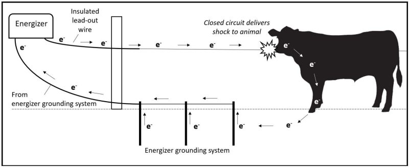
The energizer constantly sends a pulse of electrons (symbolized by “e-”) from its positive terminal to the fence wire. Electrons flow both within the wire and along its surface. If an animal touches the wire, it serves as a bridge, allowing electrons to flow from the wire through the animal and into the soil. Most electric fences in the eastern U.S. use a series of connected ground rods to create a grounding field that receives electrons in the soil and carries them back to the negative (ground) terminal of the energizer. This completes a circuit, which delivers a shock to the animal (fig. 1).
In some areas (especially in the western U.S.) where soil conditions are often dry, many people use either a continuous ground system or an earth-return system rather than the traditional grounding system described above. These grounding systems are described further in the appendix section of this publication.
What happens to electrons when nothing is touching the fence?
When no animal bridges the fence wire and soil, the circuit is incomplete. In this case, the pulse of electrons on the wire simply dissipates into the air and nearby objects through a process called induction. You may sometimes experience the effects of induction when you touch a gate that has become electrified and receive a shock (this can be remedied by grounding the gate to dissipate the induction charge). You may also experience induction when a voltmeter picks up a reading while still inches away from the wire, or when you observe livestock that appear to be smelling the current on a fence: Their wet muzzles are able to feel the induced current.
Understanding the role of resistance
Each object in the “circuit” of the electric fence system presents resistance to the flow of electrons. The energizer’s lead-out wire or cable represents the first resistance to the pulse of flowing electrons. Therefore, it is especially important that this first component be large diameter (ideally 12 ½ gauge) to minimize resistance to electron flow at the very start. Using bare, high-quality galvanized fence wire can work, but ideally you would use insulated lead-out cable. This is a requirement when going through or around buildings or other objects.
The best option to go from the energizer to the fence is high conductive lead-out cable, which is an aluminum- coated wire with heavy-duty plastic insulation. It is approximately three times as conductive as galvanized steel wire.
For the fence itself, quality 12 ½ gauge galvanized smooth fence wire provides little resistance. It is worth noting that because electricity flows on a wire’s surface in addition to within, wire with flaking or rusty coating is a poor conductor. When installing an electric fence with multiple hot wires, connect all hot wires at the beginning and end of each run of fence to minimize resistance. This creates a larger overall path for electrons to properly move along the fence with each pulse of the energizer.
Electric polywire or polytape, which contains multiple small wire filaments, has less surface area and more resistance than a single 12 ½ gauge fence wire.
Depending on the size of your energizer and the type of polywire or polytape, resistance can limit the amount of this type of fence that can be effectively electrified. This is often observed as a voltage drop on the fence as you move farther away from the energizer, and it’s a good reason why these products should only be used as temporary fence wire and not for permanent applications over long distances.
The resistance of an animal touching the fence is generally low. As electrons flow from the animal to the soil, however, they encounter greater resistance. While soil is conductive, resistance of soil varies depending on its mineral and moisture content. Soil moisture is a major factor in the performance of an electric fence, so you should become familiar with the voltage range within which your fence operates across the season. To ensure effective control of livestock, the fence should maintain at least 5,000 volts even during dry weather.
Finally, the grounding system represents a potentially large source of resistance that can limit current flow back to the energizer to complete the circuit. Ensuring ground rods are properly installed and adding additional ground rods are the main ways to increase the effectiveness of your fence, assuming there are no issues with the energizer or any electric shorts in the fence.
More information can be found in another publication in this series, “Electric Fencing: How to Install a Grounding System” (SPES-691P).
Training animals to electric fence
Unlike other fences that create a physical barrier, an electric fence is a psychological barrier. Livestock should be “trained” to the electric fence, ensuring that their first exposure to it is in a low-stress environment where they can explore and receive a memorable shock. For example, place animals in a receiving area or sacrifice pasture near feed or water where they are sure to encounter it. Some producers place a strand of temporary electric wire several feet inside of an existing permanent fence to ensure livestock encounter it as they travel the fence line. Make sure the fence voltage reads at least 5,000 volts during training. Livestock that are well-trained to electric fencing will typically respect it well thereafter. Many producers state that if their fences are routinely kept at a minimum of 3,000-5,000 volts for cattle or 7,000 volts for sheep, the psychological impact is reinforced so well that their livestock will respect the fence even during periods when electricity is lost.
Fence wire height and spacing
Installing hot wires at the correct height is an often- overlooked part of the process of ensuring a fence’s effectiveness. For a fence to be successful, not only must it maintain a high voltage, the hot wire(s) must also be located at the right height so that animals receive a shock in the face. This varies by animal species and class of livestock (table 1). On fences with multiple wires, it is generally recommended to space wires
no more than 10 inches apart; any more would allow livestock to put their head between the wires and receive a shock on the chest or back of the neck, causing them to react by moving forward through the fence.
It is generally not recommended to install fences with alternating hot and cold wires. If you choose to do so, space wires at least 6 inches apart to minimize induction from hot to cold wires, as the wires can leak current, especially when fenceposts are wet.
| Animal Type | Fence Type |
Wire Spacing, Inches Above Ground Level |
|---|---|---|
Cattle |
Electric 1-wire high tensile smooth |
26-32 |
Electric 2-wire high tensile smooth (both hot) |
20, 32 |
|
Electric 3-wire high tensile smooth (min. 2 hot) |
18, 30, 42 |
|
Electric 4-wire high tensile smooth (min. 2 hot) |
12, 22, 32, 42 |
|
Electric 5-wire high tensile smooth (min. 2 hot) |
12, 20, 28, 36, 44 | |
Goats & Sheep |
Electric 3-wire high tensile smooth (all hot) |
8, 18, 30 |
Electric 4-wire high tensile smooth (all hot) |
6, 16, 26, 36 |
|
Electric 5-wire high tensile smooth (all hot) |
6, 12, 18, 28, 38 | |
Horses |
Electric 3-wire high tensile smooth (all hot) |
28, 38 |
Electric 4-wire high tensile smooth (min. 2 hot) |
28, 38, 48 |
|
Electric 5-wire high tensile smooth (min. 2 hot) |
18, 27, 36, 45, 54 |
General tips for constructing an electric fence
- Use 12 ½ gauge high-tensile smooth wire with a Class 3 galvanized coating for the fence. Class 3 wire has roughly three times as much galvanization as Class 1 wire, which means greater conductivity and life expectancy of the wire.
- Use quality wire clamps, connectors, or crimps for all wire connections rather than hand wrapping if possible, especially for energizer lead-out wire and jumper wires. Poor wire connections can add significant resistance when repeated across an entire farm.
- Purchase high-quality insulators. More expensive insulators tend to have UV stabilizers and higher quality plastic that resists cracking with age and does not bleed current.
- Do not use copper in electric fencing systems. Connecting copper to other metals such as steel will quickly result in corrosion, as will the use of copper in a pulsed electrical system. The result is a reduction in the fence’s performance.
- Use only insulated lead-out cable manufactured specifically for use in going through buildings or under gates. Residential electric wire is not adequate to carry high voltage and will burn up, causing electrical shorts. Consider using high conductive aluminum lead-out cable to go any significant distance from the energizer to the fence.
- Buried insulated lead-out wire or cable can develop cracks or abrasion in the insulated coating from vehicle traffic over time. Consider sleeving buried wire with conduit when going under gates or use double-insulated lead-out cable.
- All hot wires on a multiple-wire fence should be connected at the beginning and end of each run of fence. This reduces overall electrical resistance for a hotter fence and somewhat allows the current to go around shorts in the fence. All ground wires in a continuous ground or earth return system should also be connected at the beginning and end of each run of fence. Insulated steel or aluminum lead-out cable should be used to optimize conductivity when connecting multiple fence wires or feeding electricity underneath gates.
Appendix
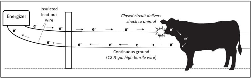
In a continuous ground system (fig. 2), a nonelectrified (ground) wire is installed on the fence and connected to the ground terminal of the energizer. When an animal touches the hot and ground wires at the same time, electrons return to the energizer through the ground wire to complete the circuit.
In an earth return system (fig. 3), a continuous ground wire on the fence is connected directly to its own grounding system, which sends electrons through the soil to the energizer’s grounding system. This helps transfer electrons directly to deeper soil and moisture. If soil moisture is adequate, an earth return system is also able to complete a circuit conventionally through an animal bridging the fence’s hot wire and the soil.

Acknowledgements
Thank you to the technical reviewers for this publication: Steve Jones, Conservation Specialist, John Marshall Soil and Water Conservation District; Sydney Beery, Sydney Beery Electric Fence Energizer Repair; Phil Blevins, Extension Agent, Washington County; and Scott Jessee, Extension Agent, Russell County.
Virginia Cooperative Extension materials are available for public use, reprint, or citation without further permission, provided the use includes credit to the author and to Virginia Cooperative Extension, Virginia Tech, and Virginia State University.
Virginia Cooperative Extension is a partnership of Virginia Tech, Virginia State University, the U.S. Department of Agriculture (USDA), and local governments, and is an equal opportunity employer. For the full non-discrimination statement, please visit ext.vt.edu/accessibility.
Publication Date
May 9, 2025
