Cross-Laminated Timber (CLT) panels Fact Sheet
ID
CNRE-143NP
What are CLT panels?
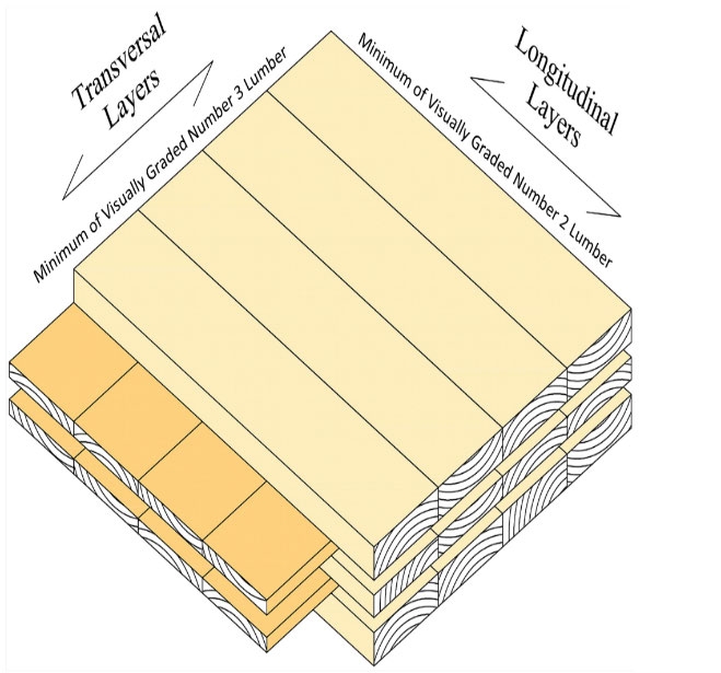
CLT panels are comprised of lumber or composites layers with boards stacked crosswise at 90-degree angles and glue together. See Figure 1. An odd number of layers, three to seven per panel, is common to fabricate CLT panels. Some of the companies in Europe are manufacturing up to nine layers.
History
CLT was invented in the early 1990s in central Europe and is now considered an alternative construction material to mid and high-rise buildings across the globe. Based on uses, CLT panels are two types: structural or non-structural. Structural CLT panels are used in structural construction and manufactured under the criteria specified by APA- PRG 320 standard in North America. However, non- structural CLTs can be manufactured from any lumber species and types that satisfy the user requirements. Non-structural CLT panels are commonly used as access mats as an alternative to bolted mats. Table 1 shows a list of CLT manufacturing facilities in the USA.
| Company Name | City | State | Products |
|---|---|---|---|
| DR Johnson | Riddle | OR | All CLTs |
| SmartLAM | Columbia Falls | MT | All CLTs |
| SmartLAM | Dothan | AL | All CLTs |
| Freres Lumber | Lyons | OR | All CLTs |
| Sterling | Phoenix | IL | CLT Mats only |
| Sterling | Lufkin | TX | CLT Mats only |
| Spartan Mat | Peach Bottom | PA | CLT Mats only |
| Structurlam | Conway | AR | All CLTs |
| Mercer Mass Timber | Spokane Valley | WA | All CLTs |
| Vaagen Timbers | Colville | WA | All CLTs |
| Texas CLT | Magnolia | AR | All CLTs |
| Viking Mat Company | Eden Prairie | MN | CLT Mats only |
| Yak Mat | Columbia Falls | MS | CLT Mats only |
North American Standard
In North America, CLT mills only qualify to produce CLT panels for structural applications after getting certified through the ANSI/APA-PRG 320 standard. The Engineered Wood Association grants the qualification, and each mill should certify both process and product for commercial production of CLT panels for structural application.
Lumber requirements
Sawn lumber for CLT manufacturing must be from softwood species with a specific gravity greater than 0.35. The American Lumber Standards Committee (ALSC) must qualify softwood species under PS 20 for manufacturing structural CLT panels. Lumber to be used in CLT manufacturing must be kiln-dried to a moisture content of 12±3%. Cross-laminated timber layers parallel to the outside layer must be a minimum of visually graded Number 2 and visually graded Number 3 for the perpendicular layers. The thickness of individual lumber must be 15.9 mm to 50.8 mm. The common lumber choice is 60.96 mm to 241.3 mm in width. Table 2 shows the approved CLT layouts and Table 3 lists the technical specifications of each approved CLT grade in the ANSI/APA-PRG 320 standard.
CLT Panel Manufacturing
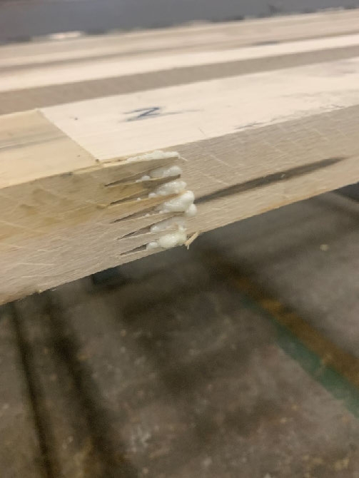
The production process of the CLT panels starts with a quality check of the available lumber regarding sizes, moisture content, and lumber grade. First, the lumber is bonded lengthwise using finger joints (Figure 2).
| CLT Grades | Specification details. |
|---|---|
| E1 | 1950f-1.7E Machine Strength Rated (MSR) Spruce-Pine-Fir (SPF) in all parallel layers and No. 3 SPF in all perpendicular layers |
| E2 | 1650f-1.5E MSR Douglas Fir-Larch lumber in all parallel layers and No. 3 Douglas Fir-Larch lumber in all perpendicular layers |
| E3 | 1200f-12E MSR, Northern Species, Eastern Softwoods or Western Woods in all parallel layers and No. 3, Northern Species, Eastern Softwoods or Western Woods all perpendicular layers |
| E4 | All Parallel layers: 1950f -1.7E MSR Southern pine lumber and All Perpendicular layers: No. 3 Southern pine lumber |
| E5 | All Parallel layers: 1950f -1.7E MSR Hem-fir lumber and All Perpendicular layers: No. 3 Hem-fir lumber |
| V1 | All Parallel layers: No. 2 Douglas Fir-Larch and All Perpendicular layers: No. 3 Douglas Fir-Larch lumber |
| V1(N) | All Parallel layers: No. 2 Douglas Fir-Larch (North) and All Perpendicular layers: No. 3 Douglas Fir-Larch lumber (North) |
| V2 | All Parallel layers: No. 1/No. 2 SPF lumber and All Perpendicular layers: No. 3 SPF lumber |
| V3 | All Parallel layers: No. 2 Southern pine lumber and All Perpendicular layers: No. 3 Southern pine lumber |
| V4 | All Parallel layers: No. 2 SPF lumber and All Perpendicular layers: No. 3 SPF lumber |
| V5 | All Parallel layers: No. 2 Hem-fir lumber and All Perpendicular layers: No. 3 Hem-fir lumber |
| S1 | 2250f-1.5E LVL in all longitudinal and transverse layers |
| S2 | 1900f.1.3E LSL in all longitudinal and transverse layers |
| S3 | 1750f-1.3E OSL in all longitudinal and transverse layers |
| CLT grade | Layers | Strength Value | |||||||
|---|---|---|---|---|---|---|---|---|---|
| Major Strength Direction | Minor Strength Direction | ||||||||
| FbSeff,0 N -mm/m | EIeff, 0 N-mm2/m | GA eff, 0 (N/m of width) | Vs,0 (kNhn of width) | FbSeff,90 N - mm/m | Eieff 90 N-mm2/m | GA, eff 90 (N/m of width) | Vs,90 (kNhn of width) | ||
| E1 | 3 | 42 | 1,088 | 7.3 | 35 | 1.4 | 32 | 9.1 | 12 |
| 5 | 98 | 4,166 | 15 | 58 | 12 | 837 | 18 | 95 | |
| 7 | 172 | 10,306 | 22 | 82 | 29 | 3,220 | 27 | 58 | |
| E2 | 3 | 36 | 958 | 8 | 44 | 0.94 | 36 | 8.2 | 15 |
| 5 | 83 | 3,674 | 16 | 74 | 8.2 | 930 | 16 | 44 | |
| 7 | 146 | 9,097 | 24 | 103 | 19 | 3,569 | 25 | 74 | |
| E3 | 3 | 26 | 772 | 5.3 | 30 | 0.92 | 23 | 6.4 | 10 |
| 5 | 60 | 2,956 | 11 | 50 | 8 | 605 | 13 | 30 | |
| 7 | 106 | 7,313 | 16 | 70 | 18 | 2,325 | 19 | 50 | |
| E4 | 3 | 36 | 958 | 8 | 37 | 1.4 | 36 | 8.2 | 12 |
| 5 | 83 | 3,674 | 16 | 62 | 12 | 930 | 16 | 37 | |
| 7 | 146 | 9,097 | 24 | 87 | 29 | 3,569 | 25 | 62 | |
| E5 | 3 | 15 | 1,023 | 8 | 44 | 0.94 | 36 | 8.7 | 15 |
| 5 | 35 | 3,922 | 16 | 74 | 8.2 | 930 | 17 | 44 | |
| 7 | 61 | 9,708 | 24 | 103 | 19 | 3,571 | 26 | 74 | |
| V1 | 3 | 18 | 884 | 7.2 | 35 | 1.4 | 32 | 7.5 | 12 |
| 5 | 41 | 3,388 | 14 | 58 | 12 | 837 | 15 | 95 | |
| 7 | 72 | 8,388 | 22 | 82 | 29 | 3,213 | 23 | 58 | |
| V1(N) | 3 | 17 | 1,023 | 8 | 37 | 1.4 | 36 | 8.7 | 12 |
| 5 | 38 | 3,922 | 16 | 62 | 12 | 930 | 17 | 37 | |
| 7 | 67 | 9,708 | 24 | 87 | 29 | 3,571 | 26 | 62 | |
| V2 | 3 | 51 | 1,226 | 8.9 | 43 | 6.9 | 47 | 8.9 | 14 |
| Continued from previous Table | |||||||||
|---|---|---|---|---|---|---|---|---|---|
| CLT grade | Layers | Strength Value | |||||||
| Major Strength Direction | Minor Strength Direction | ||||||||
| FbSeff,0 N -mm/m | EIeff, 0 N-mm2/m | GA eff, 0 (N/m of width) | Vs,0 (kN/n of width) | FbSeff,90 N -mm/m | Eieff 90 N-mm2/m | GA, eff 90 (N/m of width) | Vs,90 (kNhn of width) | ||
| 5 | 117 | 4,704 | 18 | 71 | 60 | 1,226 | 18 | 43 | |
| 7 | 207 | 11,647 | 27 | 99 | 138 | 4,704 | 27 | 71 | |
| V3 | 3 | 43 | 1,059 | 7.7 | 49 | 5.8 | 41 | 7.7 | 16 |
| 5 | 99 | 4,064 | 15 | 81 | 51 | 1,059 | 15 | 49 | |
| 7 | 175 | 10,064 | 23 | 113 | 116 | 4,064 | 23 | 81 | |
| V4 | 3 | 0.4 | 1,059 | 7.7 | 37 | 5.4 | 41 | 7.7 | 12 |
| 5 | 91 | 4,064 | 15 | 62 | 47 | 1,059 | 15 | 37 | |
| 7 | 161 | 10064 | 23 | 87 | 107 | 4,064 | 23 | 62 | |
| V5 | 3 | 42 | 1,088 | 7.3 | 35 | 1.4 | 32 | 9.1 | 12 |
| 5 | 98 | 4,166 | 15 | 58 | 12 | 837 | 18 | 95 | |
| 7 | 172 | 10,306 | 22 | 82 | 29 | 3,220 | 27 | 58 | |
| S1 | 3 | 51 | 1,226 | 8.9 | 43 | 6.90 | 47 | 8.9 | 14 |
| 5 | 117 | 4,706 | 18 | 71 | 60 | 1,226 | 18 | 43 | |
| 7 | 207 | 11,647 | 27 | 99 | 138 | 4,706 | 27 | 71 | |
| S2 | 3 | 43 | 1,059 | 7.7 | 49 | 5.80 | 41 | 7.7 | 16 |
| 5 | 99 | 4,064 | 15 | 81 | 51 | 1,059 | 15 | 49 | |
| 7 | 175 | 10,064 | 23 | 113 | 116 | 4.064 | 23 | 81 | |
| S2 | 3 | 43 | 1,059 | 7.7 | 49 | 5.80 | 41 | 7.7 | 16 |
| 5 | 99 | 4,064 | 15 | 81 | 51 | 1,059 | 15 | 49 | |
| 7 | 175 | 10,064 | 23 | 113 | 116 | 4.064 | 23 | 81 | |
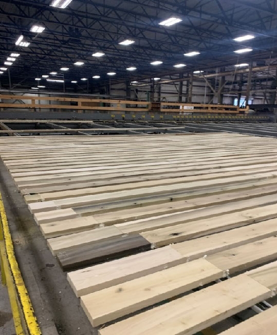
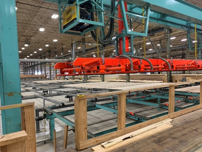
After finger-jointing, the lumber is dressed (surfaced) all four sides to ensure the required width and thickness and are trimmed to the desired length according to the designed dimension for parallel and perpendicular layers (Figure 3). All panels are assembled using a similar technique to plywood production: first, the bottom layer is placed on glue bench and the machine spreads the adhesive on top before laying adjacent perpendicular layers. See Figure 4.
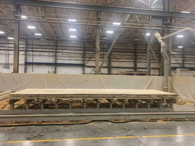
After applying adhesive, each panel is immediately pressed to form a solid CLT structure, see Figure 5. The pressing force must meet the specifications of the adhesive and lumber species. Equally distributed adequate pressure is essential over the whole CLT panel layer surface to guarantee a consistent bond line.
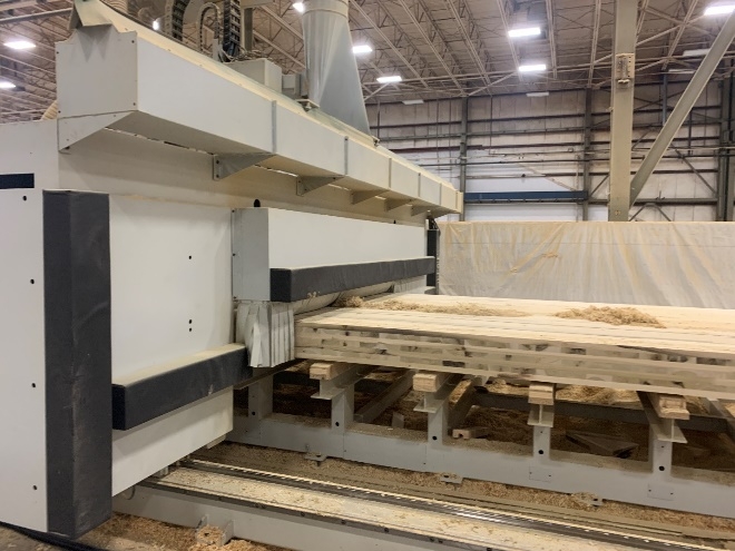
Cross-laminated timber panels from the press come with excess adhesive on the edge of the panels.
Therefore, this excess must be removed by edge trimming. Finally, all panels are dressed properly for finishing. CLT panels are customized according to the end-use by cutting, trimming, milling, and drilling to match the design specifications, see Figure 6.
CLT manufacturing's final step is product labeling using manufacturing, logistics, and on-site assembly information. The finished product is packaged to protect it from harsh weather conditions and prepared for shipping. All the assembly parts are collected at the installation site, where the structure will be constructed.
Advantages of CLT Panels
The sustainable nature of wood due to carbon sequestration and minimum embodied energy is the major environmental advantage of CLT panels compared to steel and concrete construction. Some studies concluded that an average of 26.5% reduction in global warming potential could be achieved with CLT construction compared to concrete and other construction materials (Vanova et al., 2021).
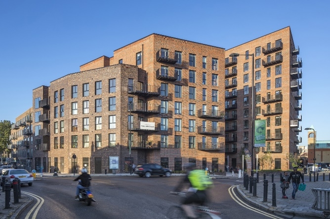
CLT panels have ease of factory prefabrication of the parts and design flexibility. This allows for precise openings for doors, windows, and other mechanical elements of the structure. Figure 7 shows the building Dalston Lane, the largest CLT structure in the World.
CLT panel construction helps to reduce onsite work and assembly. It is estimated to cut construction time by a minimum of 20% when compared to concrete construction. CLT construction also helps to reduce waste on construction sites due to prefabrication practice (Augustus; Raymond, 2019).
CLT panels have a thermal conductivity of 0.13 W/mK, better than steel and concrete structures, providing better insulation properties and CLT panels provide outstanding structural stability and stiffness. The cross-laminating of layers exhibits relatively high in-plane and out-of-plane strength, resulting in higher load-bearing capacity.
The strength and cross lamination make CLT capable of a two-way span, like reinforced concrete, providing the ease of transferring the load into two- structural directions. Higher seismic and fire resistance ability of CLT panels is the major advantage over traditional construction materials.
The fibrous nature of wood and assembly connection of CLTs provides seismic flexibility. A charred layer is formed on the CLT surface during the fire, preventing oxygen from the outside and limiting the fire from spreading much.
Construction with CLT panels results in lower- weight buildings than traditional construction systems. As a result, it requires minimum foundation work for construction.
Disadvantages of CLT Panels
Currently CLT panels are more expensive than traditional construction such as steel or concrete. Its price depends on the need for transportation, foundation work, assimilation cost, and CLT grade. Transportation is a significant cost factor, so it is less attractive if the construction requires long- distance hauling. CLT panels could be more cost- effective for mid, and high-rise buildings only, so they will not be the primary choice for residential housing to compete with timber frame construction.
Limited availability and a long waiting time are other limitations as there are very few CLT industries in operation. CLT manufacturing requires huge lumber volumes and is adding additional demand for structural grade lumber.
Finally, obtaining desired acoustic insulation may be a problem and it requires the use of additional materials such as light concrete to increase acoustic insulation.
Acknowledgment
The Department of Sustainable Biomaterials at Virginia Tech would like to thank the Softwood Export Council (SEC) for providing the funding for the production of this fact sheet.
References
APA-PRG 320. (2018). Standard for Performance- Rated Cross-Laminated Timber -American Standard. www.ansi.org
Augustus; Raymond, E. (2019, November 20). CLT - What is it and when does it make sense? — CE Solutions - Structural Engineers. https://www.cesolutionsinc.com/blog/2019/11/20-advantages-clt-concrete-steel-cpcd5
Fragiacomo, M., Menis, A., Clemente, I., Bochicchio, G., & Ceccotti, A. (2012). Fire Resistance of Cross-Laminated Timber Panels Loaded Out of Plane. Journal of Structural Engineering, 139(12), 04013018. https://doi.org/10.1061/(ASCE)ST.1943- 541X.0000787
Schuler Timothy A. (2018). Dalston Works, the Largest CLT Building in the World | Architect Magazine. https://www.architectmagazine.com/technology/a rchitectural-detail/dalston-works-the-largest-clt- building-in-the-world_o
Vanova, R., Stompf, P., Stefko, J., & Stefkova, J. (2021). Environmental Impact of a Mass Timber Building—A Case Study. Forests 2021, Vol. 12, Page 1571, 12(11), 1571. https://doi.org/10.3390/F12111571
There will be three fact sheets on mass timber products including cross-laminated timber, gluelams, and structural composite lumber. Each fact sheet will be also published in spanish.
Virginia Cooperative Extension materials are available for public use, reprint, or citation without further permission, provided the use includes credit to the author and to Virginia Cooperative Extension, Virginia Tech, and Virginia State University.
Virginia Cooperative Extension is a partnership of Virginia Tech, Virginia State University, the U.S. Department of Agriculture (USDA), and local governments, and is an equal opportunity employer. For the full non-discrimination statement, please visit ext.vt.edu/accessibility.
Publication Date
February 21, 2022